quincy
|
I was Commisioned to make the Weapon of a Quincy. I was comissioned by a friend in England.
As stated in the Previous page Quincy are like Holy Priests and are the Opposite of Shinigami, this holds true in their weapon of choice, where as Soul Reapers use Swords, Quincy use bows. Also in the series, where as Soul Reapers purify the souls of Hollows, Quincys destroy a Hollows soul. The character main Quincy character in the Bleach series is Uryu Ishida. |

|
|
Concept & Reference
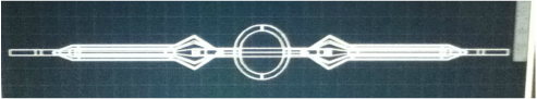
The Client (Shane Blackwell) commissioned me to make this product for him. This Bow is the Primary Weapon for a Quincy Anti-Hero called Uryu Ishida Delivery was to take place at MCM London May 2015. From the Photo I identified basic length structure. I also complied with my clients request for it to be 1.8m long and detachable at the Handle. Communication with the client began at the end of October 2014 Communication continued throughout the whole process. The Prop was to be completed in time for May 2015 |

|
Thought process
I started by looking for reference images from the series as well as existing props of the character.
Using the specifications given to me by the client , I identified the structure proportionally using the length as a scale marker.
With a rough outline of the size I created a MK.I prototype, which allowed me to visualize the full scale of the build.
Realizing that my prototype was too wide, I returned to the reference images and re-evaluated the dimensions.
This resulted in my MK.II prototype, which was accurate to my final build.
Using the data from my MK.II, I compiled all the data into a full scale plan with elevations to show hidden detail.
Using AutoCAD (2014) I made a 3D Model of the Bow, which I theorized to make by sending it to be commercially 3D Printed. Unfortunately it was unfeasible due to excessive mass/area occupied in the 3D printer. It would have been exorbitantly expensive, even with my nesting of the 3D parts to reduce area and thus costs.
I looked for the next suitable material in the sizes I required, I was looking primarily at wood, specifically Pine or MDF. If I had more specialized tools I would have looked into Plastics, in order to reduce waste and make the product lighter.
Final assemble was completed in England, within a week of the Event as size constrains were an issue in the transport of the product.
|
PROTOTYPING for Scale Adjustment
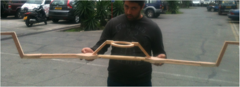
MK. I Prototype This was my MK. I Prototype with which I identified problems with my original measurements.
I had made 1 solid ‘limb’, which I used to make 2 cut outs of 5mm Plywood. The handle (40mm Ø), had 2 flats, cut out on each extremity which allowed me to attach the plywood ‘limbs’. The prototype helped me identify that the limbs and the handle were too wide. |

|

|

|
PLANNING
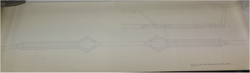
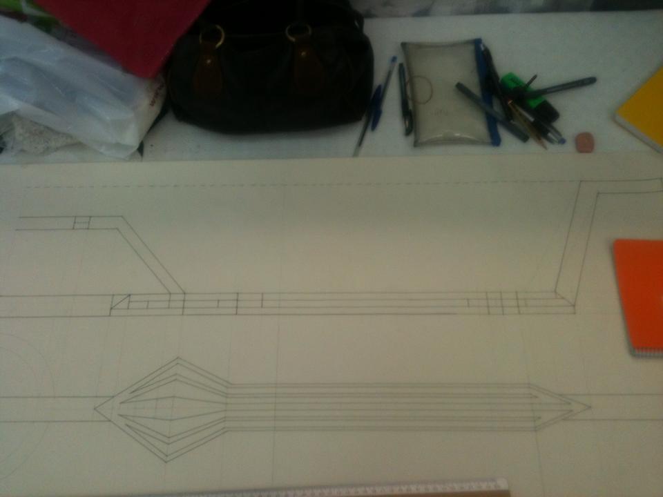
Using the MK.I prototype and plans. I adjusted my measurements and made flat (top elevation) to get my scale correct.
To be able to gauge the scope of the project I drew the plan at Scale 1:1.
This allowed me to see the entirety of the project and make corrections as neccesary for all the element to ‘fit’ the scale relative to the reference image.
Once I made my MK.II (covered below) I completed the plan, by including a side elevation.
|

|

|
PROTOTYPING
MK. II Prototype
MK. II Prototype
|
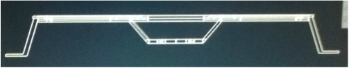
My MK.II was made from 9mm plywood sheets, with spines built in for structural integrity.
I followed my Plan using the top elevation for my main sized. I adapted the rest of the undercarriage. I ‘Saw’ (seeing without seeing) the forces and need of support material, to be able to strengthen the limbs, hold the handle in place, hold the tips and the handle ring. This prototype is not disassemblable, but give accurate proportions for the bow, as per my clients specification. The handle collet has an internal diameter of 15cm and an external of 20cm. The handle is also different as it has been reduced to 30mm Ø. The client was pleased with the progress at this stage. The due date for this project was May 2015. MK.II Prototype was completed during the month of November 2014 |

|
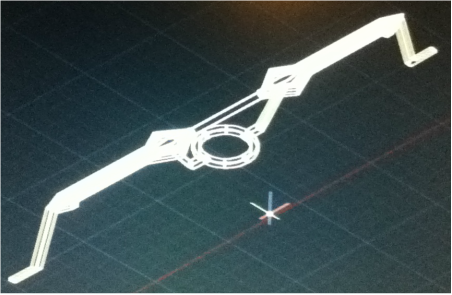
CAD & 3D MODELING
|
Being that I had made the Plan on Paper at a 1:1, I had all my measurements at an approved scale. (client approved size of product)
I began developing my AutoCAD (CAD design Program, 2010) skills, in order to not have too many paper plans/scrolls. I began by replicating the 2D plans in AutoCAD, then moving on to fleshing out the plan using generic 3D structures, extrusion and subtraction commands. |
|
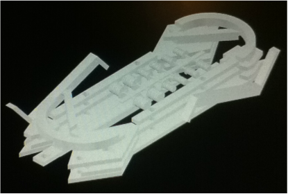
THEORIES (3D PRINTING)
|
Due to my use of AutoCAD software, I looked into 3D printing due to the ‘low-cost’ and ‘rapid-prototyping’ abilities it seemed to imply.
My research led me into a rabbit hole of different printers, commercial 3D printing firms etc. The Commercial 3D Printing firms, seemed like the best option for this project due to its size. The printing firm estimated £5 per cubed cm. The full length product was 180cm*20cm*20cm making it 72000cm3. I disassembled the product onto its components and nested the objects into the smallest space possible, while leaving a minimum of 5mm between pieces. But it was still at lot of area which then increased the price. Being that the client wanted the product disassemblable, I researched and developed Keys, to aid in assembly and dismantle of the product. Unfortunately it was not feasible but I believe I learnt much in throught this theory |

|
MATERIAL CONSIDERATION
Being that I am a carpenter and that I was in the workshop during my training, I developed an affinity for the use of wood.
I considered Pine, MDF and other Soft, Hard and Composite woods.
I ended up choosing Pine as my material of choice due to it being light, cheap, easy to shape.
I decided that MDF was a bad choice due to its poor performance vs the elements. (water/rain)
The pine was easy to shape with basic tools. Due to the size of the product, its light weight helped in keeping the product manageable and due to the amount of material needed its low value was also a factor.
Progress Notes
Using the AutoCAD files, I created paper templates of all the separate pieces , thus being able to mark the lumber. The pieces didn’t have any tolerances set, as such the pieces required slight adjustment with sandpaper for a snug fit.
The components were given two coats of acrylic spray paints, sanding between the layers, then sealing with lacquer.
Main assembly was done in my house. Where large components were glued and clamped in place as they set.
Transport to London was by plane, so all components had to fit into my suitcase. I also packed a toolbox with relevant tools/equipment to finalize construction.
I finished construction three days before the start of the event, I waited a day from landing to allow the lumber to acclimatise to the different weather conditions.
Dome Capped screws were used to add extra support and as accent pieces.
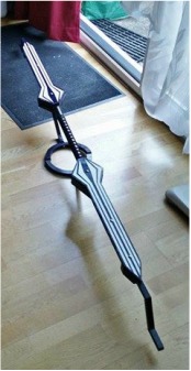
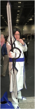
Final Product
|
The Final Product was Delivered on time to the Client.
A modification I did to the product was to lay a ‘Katana’ wrap along the handle of the product. I left one end short so that the client would know which end would slip out of the limb, for ease of transport. The hand collet was cut in two, attached by a stem to each limb allowing for easy separation. The client stated that he was impressed with the craftsmanship, and the attention to detail. |
|
|
